Design Detail
The first version of my Lehman seismometer went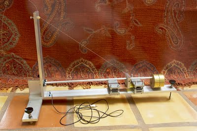 into operation in the summer of 2008. It had a 0.6m long beam and a 2 kg mass at the end and used the Chapman magnet and coil design. The resonant period was 23 seconds and set up in the E-W direction. One problem was that it was built using 3.0 inch wide and 0.5 inch thick aluminum bar stock. The 3 inch width did not allow easy movement of the coil magnet and damping magnet. In the spring of 2010, 2 new Lehman's were put together, but used 2.5 inch wide aluminum bar material and thus allow easy sliding of the Chapman magnets on the bar surface for damping adjustment. The figure shows the new Lehman.
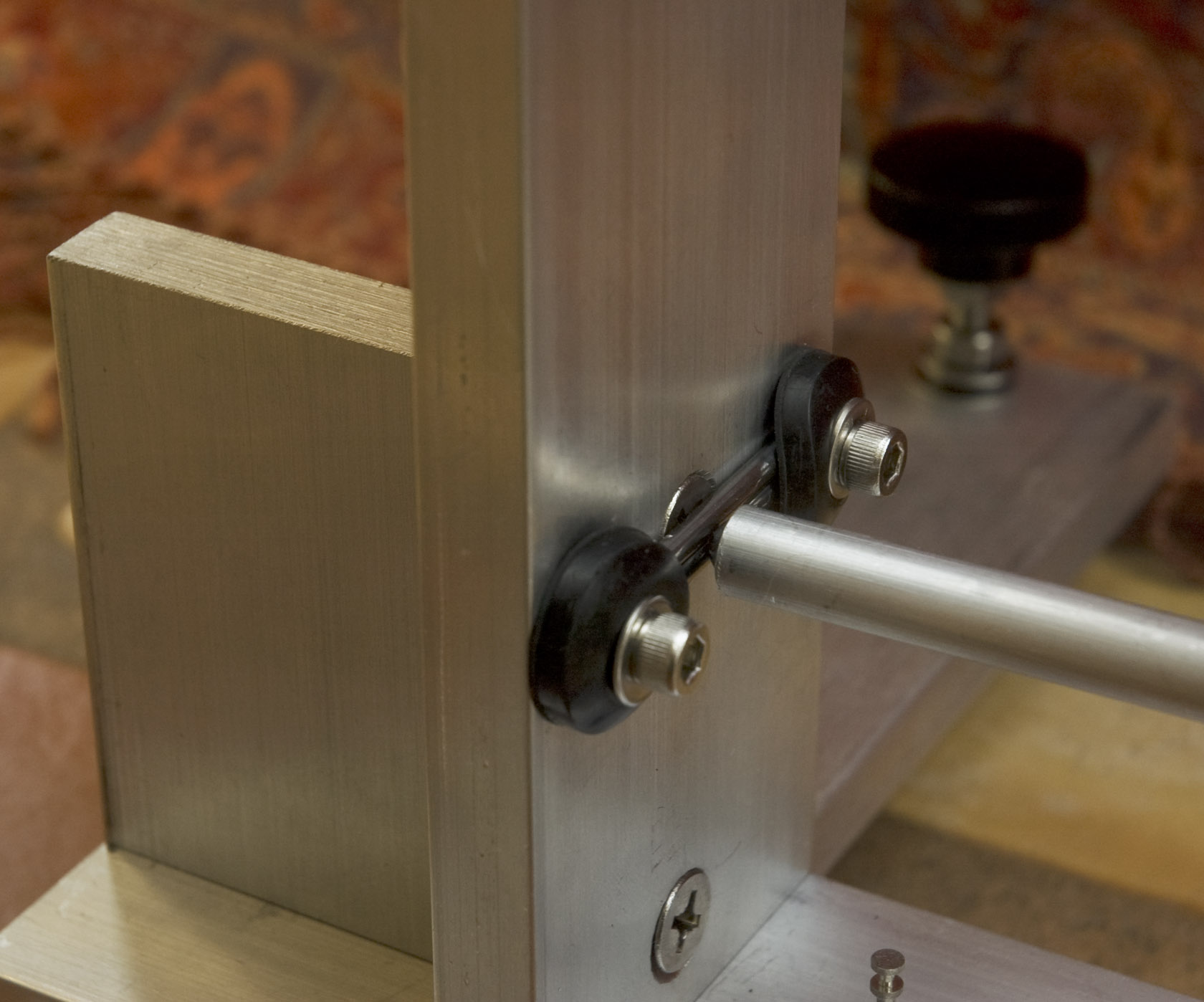 The lower bearing consists of two 1/8" diameter tungsten carbide rods and a 1/4" diameter ball bearing made from silicon carbide mounted in the end of the seismometer's beam. Tungsten carbide and silicon carbide are extremely hard materials and make an ideal bearing assembly. The tungsten rods form a channel for the silicon carbide ball bearing to seat. The weight of the mass and the support system force the beam into the 2 rods and thus keeping its position secure. The tungsten rods as supplied have a centerless ground finish. I had the bright idea to polish the rods to a mirror finish hoping to decrease any friction at the bearing. I used diamond pastes in a couple steps finally using a 1um paste to achieve the mirror finish. I mounted the rods in place and adjusted the seismometer to see what resonant period I could achieve. To my surprise, I could only achieve an 18 second resonant period before the system became unstable. A few minutes on the couch contemplating what had happened, I realized that
 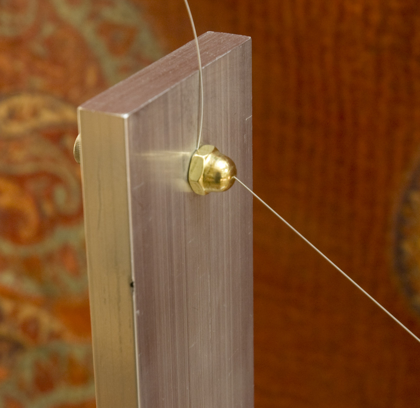 the mirror finish on the rods provided a slippery surface for ceramic ball bearing. As the beam moved back and forth while optimizing resonant period, the ball was also moving in the opposite direction and thus making the system unstable as the period was increased. The polished rods were replaced with the centerless ground finish and a 27-28 second resonant period was achieved quickly.The beam is supported at the opposite end by an 0.018" diameter guitar string fastened to a support bracket. The other end of the guitar string is passed through a 1/4-20NC brass acorn nut.
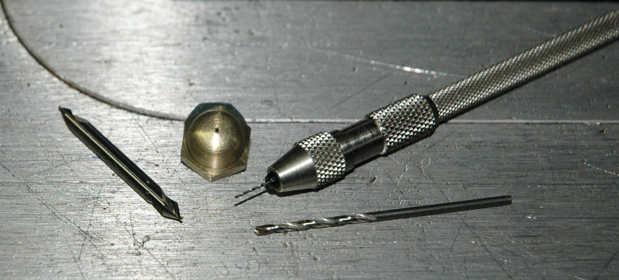
The acorn nut has a 0.020" diameter hole drilled into it. The figure shows the tools to drill the 0.020" diameter hole in the brass acorn nut. The 'large' drill bit is 0.062" in diameter. The very smallest drill is 0.020" diameter. The hand-tighten drill chuck is mounted in the drill press in order to drill the hole in the acorn nut.
Magnets and Coil Pickup
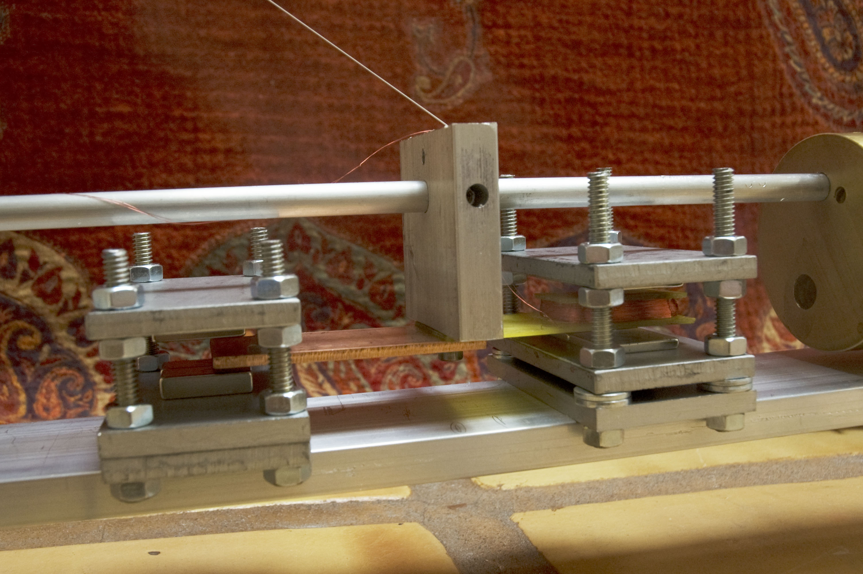 The pickup coil and eddy current damper are mounted to the same bracket as the guitar string.
The pickup coil and magnet assembly follow the Chris Chapman design. The first coil built had 1500 turns of #38 gauge magnet wire with 330 ohms resistance. The second coil has 1850 turns with the same wire size and has 450 ohms resistance. Chris' design calls for 2500 turns and I could probably get that many turns if I wound more turns near the wider portion of the coil form. But pickup coils I built with fewer turns work very well. I used 0.125 inch thick copper for the eddy current damper, but thinner copper or even aluminum will work just as well. 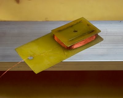
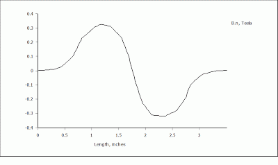
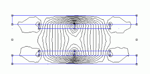 The coil magnet is on the right side and the magnet for seismometer damping is on the left. The coil magnet assembly uses 1/8" thick NdFeB rare-earth magnet material and are 1" x 1" in size. The grade level is N42. These rare-earth magnets are extremely strong and care must be taken so that you don't pinch your fingers. They are nickel plated so that small particles don't break off. The pickup coil magnet was analyzed using the